
Build a three-blade wind turbine
Building a wind turbine for individuals is only for experienced and very knowledgeable DIY enthusiasts.
Indeed, the risks posed by a poorly designed wind turbine and a faulty electrical installation are significant. Moreover, your equipment would not be profitable and would not meet your needs.
To embark on the adventure of building a wind turbine, it is better to be very meticulous, carefully plan your project before starting, and draw precise plans and sketches.
Furthermore, the choice of materials or even elements if you decide to buy some as spare parts should be given special attention to ensure their reliability and resistance.
Building a domestic wind turbine requires at least very good knowledge in:
- mechanics: generator manufacturing,
- electricity: network creation, coupling with an inverter, a regulator with an integrated rectifier, and batteries, management of alternating current and direct current,
- physics: blade creation, wind knowledge....
Advantages and disadvantages. (Three-blade)
- The undeniable advantage is a generally faster start than a two-blade for the same wind. The torque is also greater. Manufacturing is not more complicated except for a few simple solutions aimed at optimizing balancing.
- The disadvantage, although not an obstacle, is a higher weight. The blade attachments are also a bit more complicated, however, the advantages seem to outweigh.
This adjacent table demonstrates that a well-constructed two-blade will be equivalent to a Darrieus, with about 24 to 40% efficiency. The rotation speed of a two-blade is generally fast. However, the rotation speed of a three-blade is about 4% less compared to a two-blade, but the torque will be greater, especially at startup.

Your projects
You have already built a magnificent two-blade unit, but you notice that the god Aeolus is not very favorable in your region.
Or, you note that the starting torque or the torque during the self-excitation of the alternator slows down your wind machine too much.
A three-blade wind rotor could solve this “problem”
Or, you are considering building a unit from scratch.
Your choice will be a three-blade propeller.
In all three cases, a slightly different approach to the construction of a two-blade is to be considered.
The criteria for your choice of materials, wood, aluminum, light steel, synthetic materials, will be essentially the same as those outlined for the manufacture of two-blades.
If your choice is wood, a variant in the approach should be carefully considered.
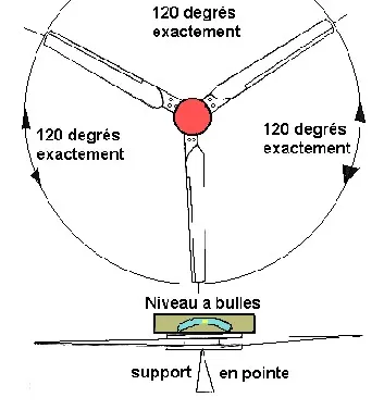
The attachments at the base of the blades must be very carefully made and will comply with the standards of blade-to-blade angles, which will be precisely 120 degrees.
Indeed, a deviation of only 4 degrees may cause your wind assembly to vibrate strongly, a vibration that could lead to destruction. See further for implications.
Let these few remarks not discourage you, nothing is impossible for those who absolutely want to achieve their goals.
Let's first see with what to make our dream three-blade (construction of the blades: wood).
Several sources of materials can be used for our propellers. Some are to be avoided. Note that ordinary plywood and balsa do not meet the strength criteria. Let's see our possibilities.
A. A straight board as indicated in palerotor will be the simplest
B and C. A laminated wood board that your carpenter will prepare for you will be an excellent solution. Two possibilities, strip lamination (B) and cross-laminated boards head to tail (C)
D. A log of wood cut into three well-dressed boards will allow you to obtain 3 boards of almost identical weight.
E. Construction according to the airplane wing or model wing method is also a possibility, although this approach is abandoned except by model makers.
F. A set of blades in aluminum or light steel is an attractive approach.
G. A set of blades in synthetic resins is the modern approach of several friends who master the use of these resins and fibers.
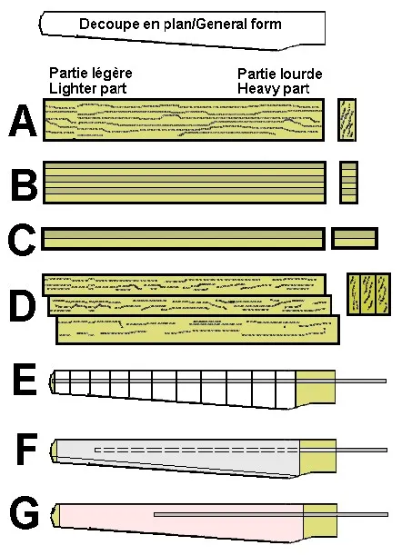
If you are considering construction with solid boards, laminated boards, or boards cut from a large log, your working method will be identical.
You can use the fixed-angle blade principle or variable-angle blade principle. As stated, a variable-angle blade is more efficient, although the initial tracing is somewhat more complicated.
If you use construction with ribs like an airplane wing or model construction, you must ensure perfect symmetry of the ribs (chords) and a very solid central support that will be both the support of the ribs and the “axis” of each blade.
An aviation-quality aluminum support is highly recommended. This type of construction, although little used nowadays, allows for significant variation in attack angles.
The covering will ideally be thin plywood (about 2mm) of exterior quality, or ideally aviation quality.
The central support, if you use all-metal construction or synthetic resins and fiberglass or carbon fibers, will have the same criteria as the construction above.
Your choice primarily depends on you, your financial means, and skill.
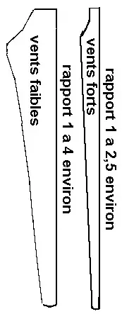
Determine the type of blade based on the wind speed in your region.
The blade for strong winds will be chosen for average annual winds of => 15 km/h.
===================>
The blade for weak winds will be useful for average annual winds of <= 12 km/h
The greatest width (chord) at the blade root will favor a quicker start during weak winds
===================>
This extra width does not hinder proper functioning when the winds become stronger
The dimensions of the blades in the drawing above are exaggerated for understanding
The two images opposite demonstrate the first step to follow if you are building your blades from solid wood or laminated wood. You draw the curves in plan and cut out the superfluous parts. Then, before shaping your blades, you must align your three blades identically. This will make your work easier later on.
No measurements are given. These depend on the dimensions you have calculated.
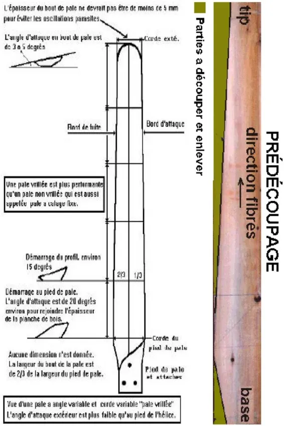
Your three future blades are cut identically. You must plane them together in such a way that they have exactly the same shape and as identical a weight as possible.
All sides are aligned as cleanly as possible to facilitate later tracing. Trace a first board according to the details of the drawing on the left.
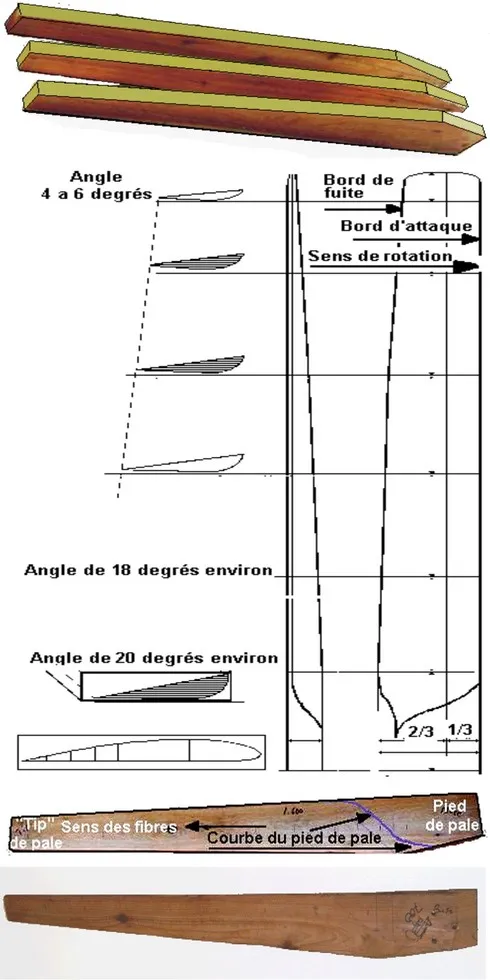
You must first thin your board starting from the point {angle 18 degrees] towards the tip. This thinning will be gradual and will depend on the length/width of your future blade. The part [angle 20 degrees] and the rest of the base will not be touched for now. A straight line will be drawn on the edge of the leading edge side, leaving at least 5mm of play for later finishing. The suggested angles will serve as a model. On the trailing edge side, you draw another straight line that will define the lower part of your profiles. You can start planing the intrados side, which is the flat or slightly concave part that will face the wind. Start from the blade root side towards the tip [Tip]. Do not make large shavings, as your board is relatively fragile and any excess may break the fibers. You can use a sander in the second step to perfect your work.
Now move on to the extrados part. This part will ideally be shaped with the help of a sander using increasingly fine grits. The curves and angles will be checked. At each step, keep a few millimeters of play for finishing. Your first blade takes shape, it should resemble the two images opposite. The curve at the blade root will be well rounded as indicated.
This first blade will serve as a model. The other two blades will be shaped identically. The finishing of your blades (wood construction) will be carried out. Pay particular attention to the leading and trailing edges and the blade root. The rounding will be as perfect as possible. The finishing before sealing and painting will be done with increasingly fine finishing cloths. A cloth of 140 to 180 will be used for a smooth surface. The sealants, either anti-humidity (strongly recommended) and/or fiber sealant, will be sanded with great care.
Finally, varnishes or paints will be applied.
Supports
The propeller supports on the motor shaft will ideally be made of steel.
This type of support will be used notably to adapt the motor shaft or alternator shaft to the brake drum support plates or fixed blade supports or even supports for a variable blade system.
The dimensions are given for a device with a diameter of 1.80 to 2.20 m.
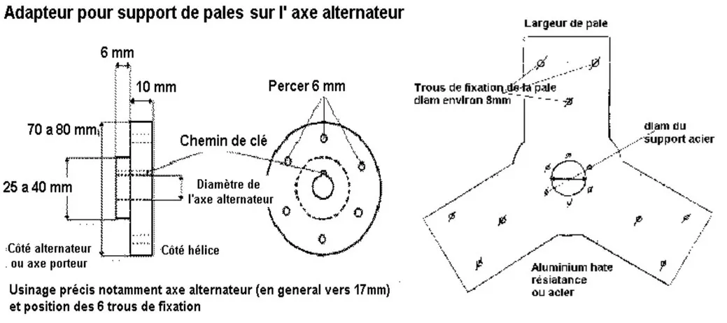
The drawing opposite shows you the simple assembly principle.
The precisely machined support is fixed by six stainless steel screws to the fixed blade support plate
Increase or decrease the dimensions according to your needs.
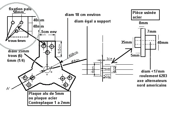
Your three-blade assembly firmly fixed on a free shaft, without restraints, you check its tracing (blades of the same length) and especially the conformity of the angles which must absolutely be 120 degrees from blade to blade.
The static balancing can be checked using a simple method with a bubble level. Image opposite.
Another solution would be to suspend your propeller group using a wire attached to the ceiling.
Your motor group is now complete if you have followed these basic instructions.
You can now attach this group to the nacelle and the shaft of your alternator or the supporting shaft.
Perform a test on a temporary pole 2 to 3 meters high. Check that your wind rotor turns perfectly and without jerks. Correct any imbalances. Even a slight angle error or imbalance can bring everything down, so... it's better to spend a few minutes or hours checking and re-checking before placing your machine at the top of its tower.
A carefully made three-blade will offer hundreds of hours of trouble-free operation.
An incomparably smooth rotation and a torque at equal diameter, much higher than a two-blade.
More and more industrial manufacturers are choosing the three-blade. Not without reason.